Surface Finish Guidelines
Enhancing Seal Performance Through Surface Finish Quality Optimization
The quality of the surface finish is directly related to the dynamic and static sealing performance. The capacity to precisely define, measure, and manage surface finish quality is vital to a seal's functional reliability and service life. Innovations in surface finish measurement equipment, capabilities, and finishing procedures have resulted in the industry undertaking functional seal testing to establish and verify surface finish recommendations for improved seal performance over the years.
SURFACE FINISH STANDARDS AND RECOMMENDATIONS FOR OPTIMAL SEAL PERFORMANCE AND LONGEVITY
Current industry standards, reference AS4716, AS5857 and AS6235 for surface finish range from 2-4 µin for HVOF applied coatings to 4-8 µin (0.1-0.2 µm) Ra for Plastic (non-elastomer) and 8-12 µin for Elastomer seals in general dynamic applications. Past industry experience suggested that surfaces smoother than 8 µin (0.2µm) did not allow for ample lubrication of seals, while surfaces rougher than 16-20 µin (0.4-0.5 µm) Ra prematurely wore seals, yielding shorter seal life. With today's surface measurement and finishing equipment, smoother surface finishes have proven to be compatible and can increase overall seal performance.
Surface finish measurement equipment and capabilities, as well as finishing procedures, have been investigated, resulting in functional seal testing to derive and verify surface finish recommendations for better seal performance. As a result, our surface finish recommendation is dependent on the dynamic sealing surface's coating or substance.
The recommendations provided below serve as a reference guide to help define the optimum surface finish for dynamic sealing applications on HVOF-applied surfaces. The following are two sets of standard guidelines for linear hydraulic exterior seals (rod) and internal (bore) dynamic sealing surfaces. The first recommendation is for High Velocity Oxygen Fuel (HVOF) applied coatings, such as Tungsten Carbide Cobalt-Chrome (Wc-Co-Cr), and the second is for dynamic sealing surfaces that are chrome plated, aluminum anodized, or bare steel. Further product-specific surface finish recommendations can be found within the product sections.1
Table 1: Surface Finish Recommendations for HVOF Surfaces
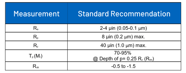
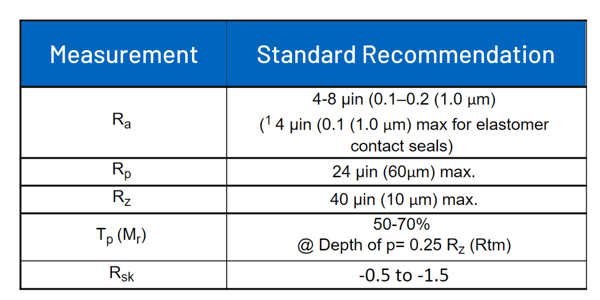
Table 2: Surface Finish Recommendations for Chrome Plating,
Anodized Surfaces, Bare Metals (Hardened) and other Non HVOF Surfaces
For internal seals (piston) the surface finish for should be 4-8 µin (0.1-0.2 µm) Ra. For surface finish recommendations on the seal groove sidewalls and groove bottoms as well as static seal interfaces, please follow recommendations in SAE AS4716, AS5857 or AS6235 seal gland standards.
TERMINOLOGY
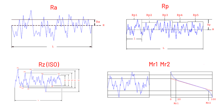
Ra - Roughness Average is the arithmetic average of absolute values of the profile height deviations from the mean line, recorded with the evaluation length. Simply put, Ra is the average of a set of induvial measurements of a surface’s peaks and valleys.
Rp - Maximum Profile Peak Height is the distance between the highest point of the profile and the mean line within the evaluation length.
Rz - Average Maximum Height of the Profile is the average of the successive values of Rti calculated over the evaluation length. This parameter is the same as Rz (DIN) when there are five (5) sampling lengths with the evaluation length.
TP (Mr) - Profile Bearing Length Ratio is the ratio of the profile bearing length to the evaluation length at a specified level.
Rsk - Skewness is a measure of the asymmetry of the profile about the mean line. A negative skewedness indicated that a greater percentage of the profile is above the mean line and a positive value indicated the great percentage is below the mean line.
Lay - refers to the dominant direction of a surface pattern, usually a repeating series of lines or grooves crated by cutting tools and abrasives. Not that all fabrication processes create a discernible lay but are random and “undirected”.
M - Mean Line is the reference line about which the profile deviations are measured. The mean line of the roughness profile is usually established by analog or digital filters with the selected cut off corresponding to the roughness sampling length.
l - Sampling Length is the nominal wavelength used for separating roughness and waviness. Also know as Cutoff Length or Cutoff.
L - Evaluation length is the specific distance along a surface profile used by measuring instruments (like a profilometer) to calculate surface finish parameters. It is recommended that evaluation length consist of five (5) sampling lengths, although it may comprise several sampling line lengths. Also known as Assessment length.
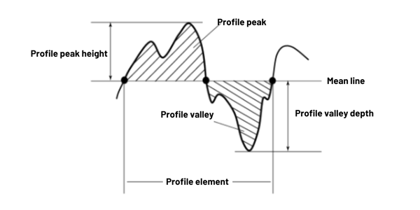
Profile Peak is the point of maximum height on a portion of a profile that lies about the mean line and between two intersections of the profile with the mean line.
Profile Valley is the point of maximum depth on a portion of a profile that lies below the mean line and between two intersections of the profile with the mean line.
PEAKS AND VALLEYS
The seal surface profile should display adequate peaks and valley and not be completely smooth. Peaks and valleys are required to optimize sealing performance and are for the retention of fluid film which provides lubrication to the seal. Having a bearing ratio (tp)of 100 percent is not recommended but for HVOF-coated surfaces, the bearing ratio is recommended to be extremely high. The values of Valley Roughness (Rv) need to be evaluated during the set-up of the production process used in the finishing of the dynamic sealing surface.
DIRECTION OF LAY
The direction or “lay” of a finish is a very important aspect of sealing performance. Its impact on the system reliability is directly connected to the finish parameters.
- A surface finish can meet the recommended surface finish values but have poor sealing performance.
- Turning, grinding, plunge grinding, honing, ballizing, polishing, and super-finishing all produce a characteristic direction or lay to a surface.
- Linear
- Cross-Hatched
- Multi
- Concentric
- Avoid a finishing method that has a strong linear lay in a reciprocating rod application or a definite concentric pattern on the shaft in a rotary application.
- Cross-hatching and non-uniform (generally grinding, multiple pass, and super-finishing) are recommended for reciprocating.
- Non-uniform (either plunge grinding or super-finishing) lay rotary seal applications.
Performance requirements of a surface need a full definition so that the right combination of surface parameters is measured and controlled. Not all these factors are critical in every application, and each application should be assessed independently to determine which of these parameters is critical to achieving the desired sealing performance. To put it another way, is it critical to not over specify the surface requirements. The parameters presented may not be necessary to completely define a surface for optimal performance. Ra is insufficient for defining and regulating a sealing surface on its own. Ra serves primarily as an amplitude metric and provides no information about the actual profile shape. Ra should be utilized as a reference value relative to the amplitude of the surface profile in sealing applications. The optimal surface profile should have a "plateau" appearance with fewer peaks but valleys to keep the seals lubricated.